
| Part No | lhold (A) | Itrip (A) |
Vmax (V) |
Imax (A) |
Pd typ (W) |
Max. (A) |
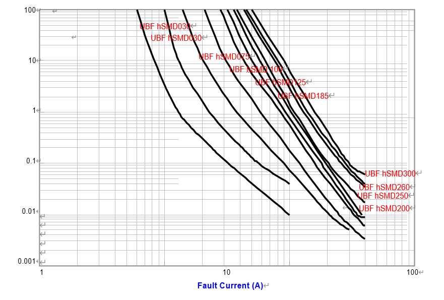
Time-to-trip (s) |
R min (Ω) |
R1 Max (Ω) |
|
| UBF | hSMD030 | 0.30 | 0.60 | 60 | 10 | 1.5 | 1.5 | 3.0 | 1.000 | 4.800 |
| UBF | hSMD050 | 0.50 | 1.00 | 60 | 10 | 1.5 | 2.5 | 4.0 | 0.300 | 1.400 |
| UBF | hSMD075 | 0.70 | 1.50 | 33 | 40 | 1.5 | 8.0 | 0.3 | 0.018 | 1.000 |
| UBF | hSMD100 | 1.10 | 2.20 | 33 | 40 | 1.5 | 8.0 | 0.5 | 0.090 | 0.410 |
| UBF | hSMD125 | 1.25 | 2.50 | 33 | 40 | 1.5 | 8.0 | 2.0 | 0.050 | 0.250 |
| UBF | hSMD150 | 1.50 | 3.00 | 33 | 40 | 1.5 | 8.0 | 2.0 | 0.050 | 0.230 |
| UBF | hSMD185 | 1.85 | 3.70 | 33 | 40 | 1.5 | 8.0 | 2.5 | 0.040 | 0.150 |
| UBF | hSMD200 | 2.00 | 4.00 | 16 | 40 | 1.5 | 8.0 | 4.5 | 0.035 | 0.120 |
| UBF | hSMD250 | 2.50 | 5.00 | 16 | 40 | 1.5 | 8.0 | 16.0 | 0.025 | 0.085 |
| UBF | hSMD260 | 2.60 | 5.20 | 6 | 40 | 1.5 | 8.0 | 20.0 | 0.020 | 0.075 |
| UBF | hSMD300 | 3.00 | 5.20 | 6 | 40 | 1.5 | 8.0 | 25.0 | 0.010 | 0.048 |
| Ihold | Hold current is the maximum current that UB Fuse can pass through without interruption at 20°C unless otherwise specified. |
| Itrip | Trip current is the minimum current that will switch the device from low resistance state to high resistance state at 20°C unless specified. |
| Vmax | The maximum voltage device can withstand without damage at rated current. |
| Imax | The maximum current device can withstand without damage at rated voltage. |
| Pd | The power dissipated from device when in the tripped state at 20°C unless otherwise specified. |
| R min | The minimum resistance of device as received from the factory at 20°C unless otherwise specified. |
| R max | The maximum resistance of device as received from the factory at 20°C unless otherwise specified. |
| R1max | The maximum resistance of device when measured one hour post trip at 20°C unless otherwise specified. |
| Max. Time-to-trip |
The maximum time for device to trip at specified current ratings at 20°C unless otherwise specified. |
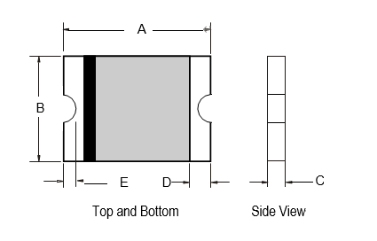
| A | B | C | D | E | ||||||
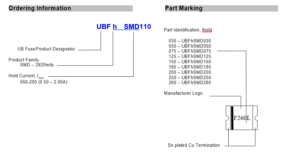
| Part No UBF hSMD |
Min. | Max. | Min. | Max. | Min. | Max. | Min. | Max. | Min. | Max. |
| 6.73 | 7.98 | 4.80 | 5.44 | 0.30 | 1.15 | 0.35 | -- | 0.30 | -- | |
| UL File Number | E 119550 |
| c-UL File Number | E 119550 |
| TUV File Number | Pending |
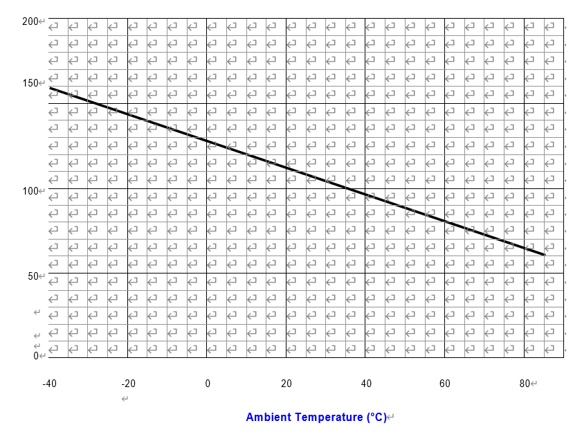
| Part No | -40 | -20 | 0 | 20 | 40 | 60 | 85 |
| UBF hSMD030 | 0.47 | 0.45 | 0.35 | 0.30 | 0.25 | 0.20 | 0.14 |
| UBF hSMD050 | 0.76 | 0.67 | 0.55 | 0.50 | 0.45 | 0.35 | 0.23 |
| UBF hSMD075 | 1.10 | 0.99 | 0.87 | 0.75 | 0.63 | 0.49 | 0.35 |
| UBF hSMD100 | 1.60 | 1.45 | 1.28 | 1.10 | 0.92 | 0.71 | 0.52 |
| UBF hSMD125 | 1.60 | 1.45 | 1.28 | 1.10 | 0.92 | 0.71 | 0.52 |
| UBF hSMD150 | 2.30 | 2.05 | 1.77 | 1.50 | 1.23 | 0.95 | 0.61 |
| UBF hSMD185 | 2.68 | 2.48 | 2.16 | 1.85 | 1.54 | 1.22 | 0.83 |
| UBF hSMD200 | 2.90 | 2.68 | 2.34 | 2.00 | 1.66 | 1.32 | 0.90 |
| UBF hSMD250 | 3.63 | 3.35 | 2.93 | 2.50 | 2.08 | 1.65 | 1.13 |
| UBF hSMD260 | 3.77 | 3.48 | 3.04 | 2.60 | 2.16 | 1.72 | 1.17 |
| UBF hSMD300 | 4.35 | 4.02 | 3.51 | 3.00 | 2.49 | 1.98 | 1.35 |
| Test | Test Conditions | Resistance Change |
| Passive Aging | +85°C, 1000 hours | ±10% typical resistance change |
| Humidity Aging | +85°C, 85% R.H., 7 days | ±10% typical resistance change |
| Thermal Shock | +85°C to -40°C, 10 times MIL-STD-202, Method 107G |
±10% typical resistance change |
| Vibration | MIL-STD-883C, Condition A | No change |
| Solvent resistance | MIL-STD-202, Method 215 | No change |
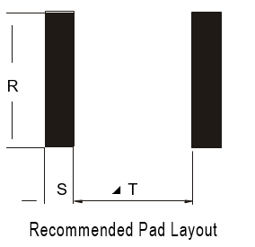
| Part No | R | S | T |
| UBF hSMD030 | 5.10 | 2.30 | 5.60 |
| UBF hSMD050 | 5.10 | 2.30 | 5.60 |
| UBF hSMD075 | 5.10 | 2.30 | 5.60 |
| UBF hSMD100 | 5.10 | 2.30 | 5.60 |
| UBF hSMD125 | 5.10 | 2.30 | 5.60 |
| UBF hSMD150 | 5.10 | 2.30 | 5.60 |
| UBF hSMD185 | 5.10 | 2.30 | 5.60 |
| UBF hSMD200 | 5.10 | 2.30 | 5.60 |
| UBF hSMD250 | 5.10 | 2.30 | 5.60 |
| UBF hSMD260 | 5.10 | 2.30 | 5.60 |
| UBF hSMD300 | 5.10 | 2.30 | 5.60 |
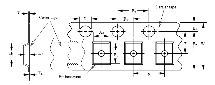
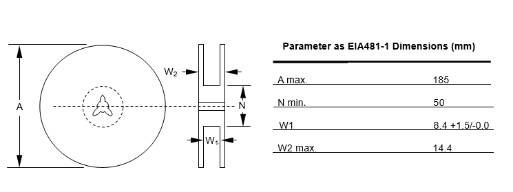
| Parameter as EIA481-1 | Dimensions (mm) |
| W | 12.00 ± 0.30 |
| P0 | 4.00 ± 0.10 |
| P1 | 8.00 ± 0.10 |
| P3 | 2.00 ± 0.05 |
| A0 | 3.50 ± 0.23 |
| B0 | 5.10 ± 0.15 |
| B1max | 8.2 |
| D0 | 1.50 +0.10/-0.00 |
| F | 5.50 ± 0.05 |
| E1 | 1.75 ± 0.10 |
| E2min | 10.25 |
| T max | 0.6 |
| T1max | 0.1 |
| K0 | 0.90 ± 0.15 |