
 |
 |
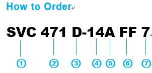
| 1 Basic Type ZnO Varistor |
2 Varistor Nominal Voltage (The first two digit indicate significaticant digits) (The 3rd digit indicate the number of zeros following) |
3 Style D : Disk Type Varistor |
| 4 Chip Element Size(Dia) 05 : Ø5mm, 07 : Ø7mm, 10 : Ø10mm, 14 : Ø14mm, 20 :Ø20mm |
5 Classification A : High Voltage(82V and above) B : Low Voltage(less then 68V) |
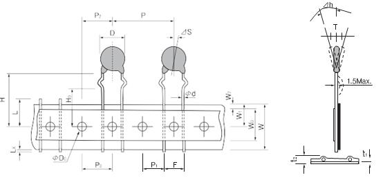
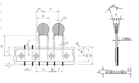
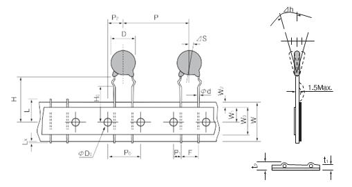
6 Packing Style & Lead Variation 7 Lead Spacing & Pitch of Component |
| Packing Style | Lead Variation | Packing Style | Lead Variation | |||||
| F |
Taping Type Flat Pack |
S | Straight Type | B |
Bulk |
S | Straight Long Type | |
| W | Kink Short Type | |||||||
| K |
In-Kink Type |
|||||||
| K | Kink Long Type | |||||||
| L | Kink Short Type | |||||||
| F |
Out-Kink Type |
|||||||
| N | Straight Short Type | |||||||
| Taping Type | Bulk Type | |||
| Code | Lead Spacing(mm) | Pitch of Component(mm) | Code | Lead Spacing(mm) |
| 5 | 5.0 | 12.7 | 5 | 5.0 |
| 7 | 7.5 | 15.0 | 7 | 7.5 |
| 8 | 7.5 | 30.0 | 1 | 10.0 |
| 9 | 7.5 | 25.4 | ||
| 1 | 10.0 | 30.0 | ||
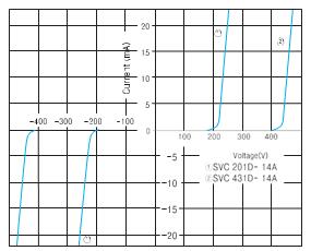
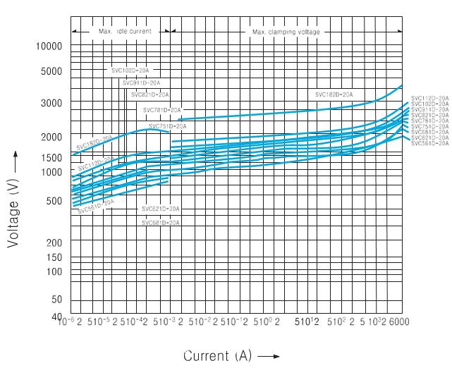
| •Small - current region of V -Ⅰcurve | •Temporary power frequency over voltage capability |
 |
 |
| B Type Withstand discharge impulse current characteristics(Typical) |
A Type •Withstand discharge impulse current characteristics(Typical) |
 |
 |
| Device Type |
Chip Element Size |
Maximum Ratings | Characteristics | ||||||||
| Applied Voltage | Transient | Nominal Varistor ④ Peak Voltage |
Max. Clamping ⑤Voltage @ Test Current(8/20㎲) |
||||||||
| RMS 50/60Hz (25℃ ) | DC (25℃ ) |
Energy ② |
Average Power Dissipation | Peak ③ Current (8/20㎲) | |||||||
| Dia (mm) | Vacm (Volts) | Vdcm (Volts) | Wtm (Joules) | Ptam (Watts) | Itm (Amps) | Vnom (Volts) | Tolerance | Vc (Volts) | Ip (Amps) | ||
| Min.(Volts) | Max.(Volts) | ||||||||||
| SVC 180D-05B SVC 180D-07B SVC 180D-10B SVC 180D-14B SVC 180D-20B | 5 7 10 14 20 |
11 |
14 |
0.3 0.8 1.5 3.5 10.0 |
0.01 0.02 0.05 0.1 0.2 |
125 250 500 1000 2000 |
18 |
16 |
20 |
40 36 36 36 36 |
1 2.5 5 10 20 |
| SVC 220D-05B SVC 220D-07B SVC 220D-10B SVC 220D-14B SVC 220D-20B | 5 7 10 14 20 |
14 |
18 |
0.4 0.9 2.0 4.0 13.0 |
0.01 0.02 0.05 0.1 0.2 |
125 250 500 1000 2000 |
22 |
20 |
24 |
48 43 43 43 43 |
1 2.5 5 10 20 |
| SVC 270D-05B SVC 270D-07B SVC 270D-10B SVC 270D-14B SVC 270D-20B |
5 7 10 14 20 |
17 |
22 |
0.5 1.0 2.5 5.0 15.0 |
0.01 0.02 0.05 0.1 0.2 |
125 250 500 1000 2000 |
27 |
24 |
30 |
60 53 53 54 53 |
1 2.5 5 10 20 |
| SVC 330D-05B SVC 330D-07B SVC 330D-10B SVC 330D-14B SVC 330D-20B |
5 7 10 14 20 |
20 |
26 |
0.6 1.2 3.0 6.0 20.0 |
0.01 0.02 0.05 0.1 0.2 |
125 250 500 1000 2000 |
33 |
30 |
36 |
73 65 65 65 65 |
1 2.5 5 10 20 |
| SVC 390D-05B SVC 390D-07B SVC 390D-10B SVC 390D-14B SVC 390D-20B |
5 7 10 14 20 |
25 |
31 |
0.8 1.5 3.5 7.0 24.0 |
0.01 0.02 0.05 0.1 0.2 |
125 250 500 1000 2000 |
39 |
35 |
43 |
86 77 77 77 77 |
1 2.5 5 10 20 |
| SVC 470D-05B SVC 470D-07B SVC 470D-10B SVC 470D-14B SVC 470D-20B |
5 7 10 14 20 |
30 |
38 |
1.0 1.8 4.5 8.5 30.0 |
0.01 0.02 0.05 0.1 0.2 |
125 250 500 1000 2000 |
47 |
42 |
52 |
104 93 93 93 93 |
1 2.5 5 10 20 |
| SVC 560D-05B SVC 560D-07B SVC 560D-10B SVC 560D-14B SVC 560D-20B |
5 7 10 14 20 |
35 |
45 |
1.0 2.2 5.5 10.5 35.0 |
0.01 0.02 0.05 0.1 0.2 |
125 250 500 1000 2000 |
56 |
50 |
62 |
123 110 110 110 110 |
1 2.5 5 10 20 |
| SVC 680D-05B SVC 680D-07B SVC 680D-10B SVC 680D-14B SVC 680D-20B |
5 7 10 14 20 |
40 |
56 |
1.2 2.5 6.5 12.0 40.0 |
0.01 0.02 0.05 0.1 0.2 |
125 250 500 1000 2000 |
68 |
61 |
75 |
150 135 135 135 135 |
1 2.5 5 10 20 |
| SVC 820D-05A SVC 820D-07A SVC 820D-10A SVC 820D-14A SVC 820D-20A | 5 7 10 14 20 |
50 |
65 |
1.7 3.5 8.0 14.0 27.0 |
0.1 0.25 0.4 0.6 1.0 |
400 1200 2500 4500 6500 |
82 |
74 |
90 |
145 135 135 135 135 |
5 10 25 50 100 |
| SVC 101D-05A SVC 101D-07A SVC 101D-10A SVC 101D-14A SVC 101D-20A |
5 7 10 14 20 |
60 |
85 |
2.0 4.0 10.0 18.0 30.0 |
0.1 0.25 0.4 0.6 1.0 |
400 1200 2500 4500 6500 |
100 |
90 |
110 |
175 165 165 165 165 |
5 10 25 50 100 |
| Device Type |
Chip Element Size |
Maximum Ratings | Characteristics | ||||||||
| Applied Voltage | Transient | Nominal Varistor ④ Peak Voltage |
Max. Clamping ⑤Voltage @ Test Current(8/20㎲) |
||||||||
| RMS 50/60Hz (25℃ ) | DC (25℃ ) |
Energy ② |
Average Power Dissipation | Peak ③ Current (8/20㎲) | |||||||
| Dia (mm) | Vacm (Volts) | Vdcm (Volts) | Wtm (Joules) | Ptam (Watts) | Itm (Amps) | Vnom (Volts) | Tolerance | Vc (Volts) | Ip (Amps) | ||
| Min.(Volts) | Max.(Volts) | ||||||||||
| SVC 121D-05A SVC 121D-07A SVC 121D-10A SVC 121D-14A SVC 121D-20A | 5 7 10 14 20 |
75 |
100 |
2.5 5.0 12.0 20.0 40.0 |
0.1 0.25 0.4 0.6 1.0 |
400 1200 2500 4500 6500 |
120 |
108 |
132 |
210 200 200 200 200 |
5 10 25 50 100 |
| SVC 151D-05A SVC 151D-07A SVC 151D-10A SVC 151D-14A SVC 151D-20A | 5 7 10 14 20 |
95 |
125 |
3.0 6.0 16.0 25.0 50.0 |
0.1 0.25 0.4 0.6 1.0 |
400 1200 2500 4500 6500 |
150 |
135 |
165 |
260 250 250 250 250 |
5 10 25 50 100 |
| SVC 201D-05A SVC 201D-07A SVC 201D-10A SVC 201D-14A SVC 201D-20A |
5 7 10 14 20 |
130 |
170 |
4.0 10.0 20.0 35.0 70.0 |
0.1 0.25 0.4 0.6 1.0 |
400 1200 2500 4500 6500 |
200 |
185 |
225 |
355 340 340 340 340 |
5 10 25 50 100 |
| SVC 221D-05A SVC 221D-07A SVC 221D-10A SVC 221D-14A SVC 221D-20A |
5 7 10 14 20 |
140 |
180 |
4.5 10.0 23.0 40.0 75.0 |
0.1 0.25 0.4 0.6 1.0 |
400 1200 2500 4500 6500 |
220 |
198 |
242 |
380 360 360 360 360 |
5 10 25 50 100 |
| SVC 241D-05A SVC 241D-07A SVC 241D-10A SVC 241D-14A SVC 241D-20A |
5 7 10 14 20 |
150 |
200 |
5.0 10.0 25.0 40.0 80.0 |
0.1 0.25 0.4 0.6 1.0 |
400 1200 2500 4500 6500 |
240 |
216 |
264 |
415 395 395 395 395 |
5 10 25 50 100 |
| SVC 271D-05A SVC 271D-07A SVC 271D-10A SVC 271D-14A SVC 271D-20A |
5 7 10 14 20 |
175 |
225 |
6.0 12.0 30.0 50.0 90.0 |
0.1 0.25 0.4 0.6 1.0 |
400 1200 2500 4500 6500 |
270 |
247 |
303 |
475 455 455 455 455 |
5 10 25 50 100 |
| SVC 361D-07A SVC 361D-10A SVC 361D-14A SVC 361D-20A |
5 7 10 14 20 |
230 |
300 |
7.5 15.0 35.0 65.0 120.0 |
0.1 0.25 0.4 0.6 1.0 |
400 1200 2500 4500 6500 |
360 |
324 |
396 |
620 595 595 595 595 |
5 10 25 50 100 |
| SVC 391D-05A SVC 391D-07A SVC 391D-10A SVC 391D-14A SVC 391D-20A |
5 7 10 14 20 |
250 |
320 |
8.0 17.0 40.0 70.0 130.0 |
0.1 0.25 0.4 0.6 1.0 |
400 1200 2500 4500 6500 |
390 |
351 |
429 |
675 650 650 650 650 |
2.55 10 25 50 100 |
| SVC 431D-05A SVC 431D-07A SVC 431D-10A SVC 431D-14A SVC 431D-20A | 5 7 10 14 20 |
275 |
350 |
9.0 20.0 45.0 75.0 140.0 |
0.1 0.25 0.4 0.6 1.0 |
400 1200 2500 4500 6500 |
430 |
387 |
473 |
754 710 710 710 710 |
5 10 25 50 100 |
| SVC 471D-05A SVC 471D-07A SVC 471D-10A SVC 471D-14A SVC 471D-20A |
5 7 10 14 20 |
300 |
385 |
10.0 20.0 45.0 80.0 150.0 |
0.1 0.25 0.4 0.6 1.0 |
400 1200 2500 4500 6500 |
470 |
423 |
517 |
810 775 775 775 775 |
5 10 25 50 100 |
| Device Type |
Chip Element Size |
Maximum Ratings | Characteristics | |||||||||
| Applied Voltage | Transient | Nominal Varistor ④ Peak Voltage |
Max. Clamping ⑤Voltage @ Test Current(8/20㎲) |
|||||||||
| RMS 50/60Hz (25℃ ) | DC (25℃ ) |
Energy ② |
Average Power Dissipation | Peak ③ Current (8/20㎲) | ||||||||
| Dia (mm) | Vacm (Volts) | Vdcm (Volts) | Wtm (Joules) | Ptam (Watts) | Itm (Amps) | Vnom (Volts) | Tolerance | Vc (Volts) | Ip (Amps) | |||
| Min.(Volts) | Max.(Volts) | |||||||||||
| SVC 561D-10A SVC 561D-14A SVC 561D-20A | 10 14 20 |
350 |
460 |
45.0 85.0 150.0 |
0.4 0.6 1.0 |
2500 4500 8000 |
560 |
504 |
616 |
920 920 920 |
25 50 100 |
|
| SVC 621D-10A SVC 621D-14A SVC 621D-20A |
10 14 20 |
385 |
550 |
45.0 85.0 150.0 |
0.4 0.6 1.0 |
2500 4500 8000 |
620 |
558 |
682 |
1025 1025 1025 |
25 50 100 |
|
| SVC 681D-10A SVC 681D-14A SVC 681D-20A | 10 14 20 |
420 |
560 |
45.0 90.0 160.0 |
0.4 0.6 1.0 |
2500 4500 8000 |
680 |
612 |
748 |
1120 1120 1120 |
25 50 100 |
|
| SVC 751D-10A SVC 751D-14A SVC 751D-20A | 10 14 20 |
460 |
615 |
50.0 100.0 175.0 |
0.4 0.6 1.0 |
2500 4500 8000 |
750 |
675 |
825 |
1240 1240 1240 |
25 50 100 |
|
| SVC 781D-10A SVC 781D-14A SVC 781D-20A |
10 14 20 |
485 |
640 |
50.0 105.0 180.0 |
0.4 0.6 1.0 |
2500 4500 6500 |
780 |
702 |
858 |
1290 1290 1290 |
25 50 100 |
|
| SVC 821D-10A SVC 821D-14A SVC 821D-20A |
10 14 20 |
510 |
670 |
55.0 110.0 190.0 |
0.4 0.6 1.0 |
2500 4500 6500 |
820 |
738 |
902 |
1355 1355 1355 |
25 50 100 |
|
| SVC 911D-10A SVC 911D-14A SVC 911D-20A | 10 14 20 |
550 |
745 |
60.0 120.0 215.0 |
0.4 0.6 1.0 |
2500 4500 6500 |
910 |
819 |
1001 |
1500 1500 1500 |
25 50 100 |
|
| SVC 102D-10A SVC 102D-14A SVC 102D-20A |
10 14 20 |
625 |
825 |
65.0 130.0 230.0 |
0.4 0.6 1.0 |
2500 4500 6500 |
1000 |
900 |
1100 |
1650 1650 1650 |
25 50 100 |
|
| SVC 112D-10A SVC 112D-14A SVC 112D-20A | 10 14 20 |
680 |
895 |
70.0 140.0 250.0 |
0.4 0.6 1.0 |
2500 4500 6500 |
1100 |
990 |
1210 |
1815 1815 1815 |
25 50 100 |
|
| SVC 182D-14A SVC 182D-20A |
14 20 |
1000 |
1465 |
24.0 400.0 |
0.6 1.0 |
4500 6500 |
1800 |
1620 |
1980 |
2970 2970 |
50 100 |
|
① The waveform of the maximum DC applied voltage is flat. When a ripple voltage as from a rectifier source is supplied make sure that the peak voltage is kept under th Vdcm An AC applied voltage(50/60Hz) form a since waveshape. When the distortion in the waveform is extensive make sure that the peak voltage is less than times the Vacm. When a ripple voltage as from a rectifier source is supplied make sure that the peak voltage is kept under th Vdcm An AC applied voltage(50/60Hz) form a since waveshape. When the distortion in the waveform is extensive make sure that the peak voltage is less than times the Vacm. |
④ Nominal varistor voltage : Vnom Indicates the varistor terminal voltage measured with a 1mA DC applied. -0.1mA DC in the case of the 0.5A and 05B series. |
| ② Energy : Wtm Transient energy ratings are given in the Wtm column of the specifications in Joules(watt-second). The rating is the maximum allowable energy for a single impulse of 2ms square-waveform current with continuous voltage applied. Energy ratings are based on a shift of Vnom of less than ±10% of initial value. |
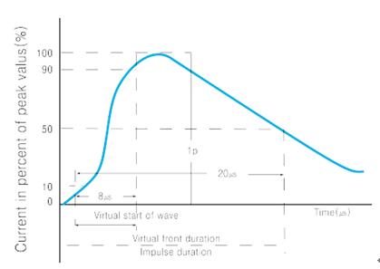
⑤ Maximum clamping voltage : Vc Indicates the peak teminal voltage measured with an 8/20㎲ impulse current applied. |
| ③ Transient peak current(Itm) The peak current rating. Itm. of varistor is based on an 8/20 ㎲ test impulse waveshape. This peak current is the maximum peak current in which the nominal varistor voltage shift does not exceed ±10% when the test impulse is applied once at 5 mimutes intervals. |
•Operating ambient temperature : -40℃ to +80℃ •Storage temperature : -40℃ to +125℃ •UL and CSA recognized(UL 1449, UL 497B or UL 1414, CSA) SVC varistors have been tested by Underwiter’s Laboratories, Inc. and Canadian Standards Association UL File No. E97754, E151195, E154171. CSA File No. LR78923. |
 |
||||||||||||||||||||||||||||||||||||||||||||||||||||||||||||||||||||||||||||||||||||||||||||||||||||||||||||||||||||||||||||||||||||||||||||||||||||||||||||||||||||||||||||||||||||||||||||||||||||||||||||||||||||||||||||||||||||||||||||||||||||||||||||||||||||||||||||||||||||||||||||||||||||||||||||||||||||||||||||||||||||||||||||||||||||||||||||||||||||||||||||||||||||||||||||||||||||||||||||||||||||||||||||||||||||||||||||||||||||||||||||||||||||||||||||||||||||||||||||||||||||||||||||||||||||||||||||||||||||||||||||||||||||||||||||||||||
A Type
|
||||||||||||||||||||||||||||||||||||||||||||||||||||||||||||||||||||||||||||||||||||||||||||||||||||||||||||||||||||||||||||||||||||||||||||||||||||||||||||||||||||||||||||||||||||||||||||||||||||||||||||||||||||||||||||||||||||||||||||||||||||||||||||||||||||||||||||||||||||||||||||||||||||||||||||||||||||||||||||||||||||||||||||||||||||||||||||||||||||||||||||||||||||||||||||||||||||||||||||||||||||||||||||||||||||||||||||||||||||||||||||||||||||||||||||||||||||||||||||||||||||||||||||||||||||||||||||||||||||||||||||||||||||||||||||||||||
|
B Type
|
||||||||||||||||||||||||||||||||||||||||||||||||||||||||||||||||||||||||||||||||||||||||||||||||||||||||||||||||||||||||||||||||||||||||||||||||||||||||||||||||||||||||||||||||||||||||||||||||||||||||||||||||||||||||||||||||||||||||||||||||||||||||||||||||||||||||||||||||||||||||||||||||||||||||||||||||||||||||||||||||||||||||||||||||||||||||||||||||||||||||||||||||||||||||||||||||||||||||||||||||||||||||||||||||||||||||||||||||||||||||||||||||||||||||||||||||||||||||||||||||||||||||||||||||||||||||||||||||||||||||||||||||||||||||||||||||||
|
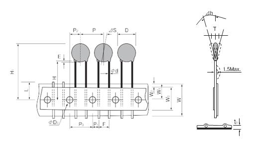
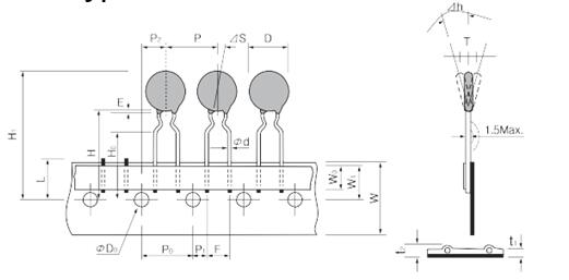
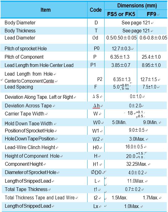
| FS5 Type | FK5 Type | FF9 Type |
 |
 |
 |
| FF7 Type | FF8 Type | |
 |
 |
 |
 |
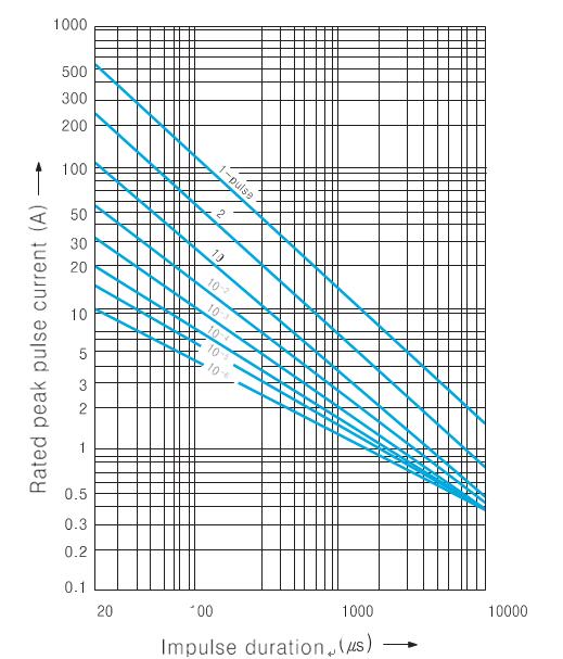
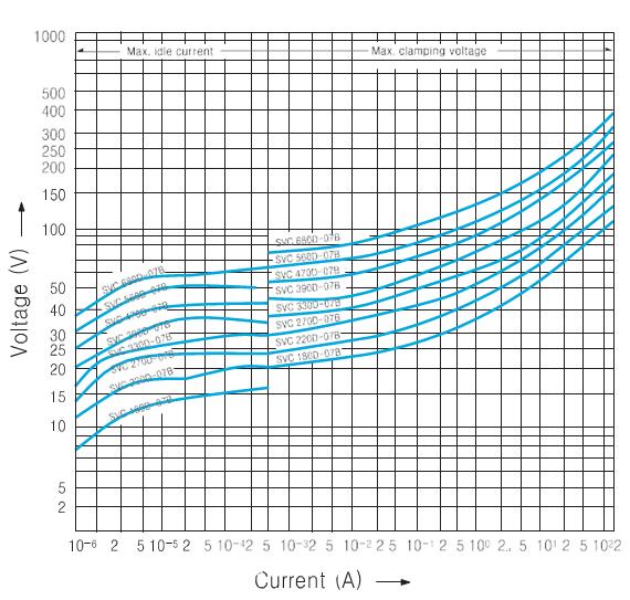
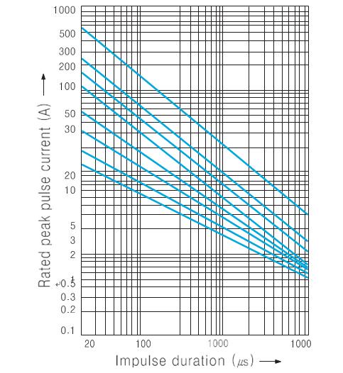
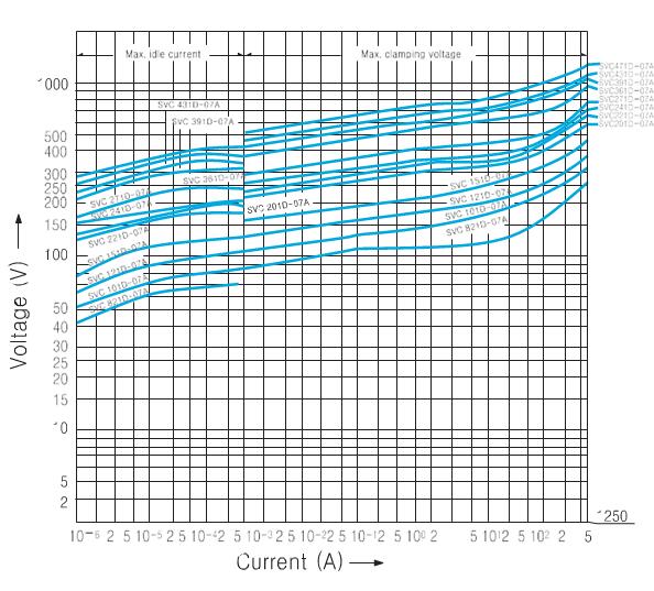
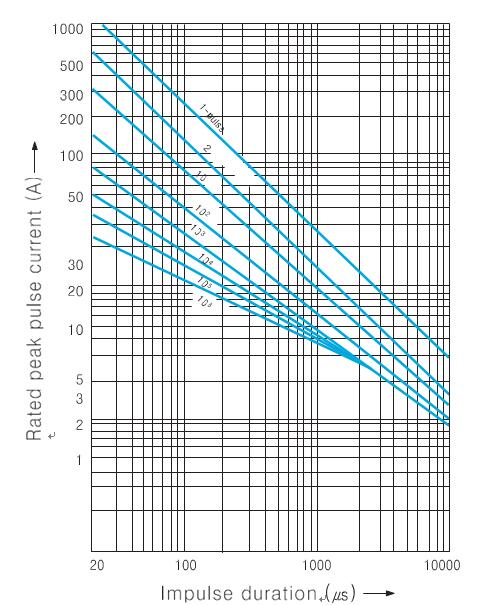
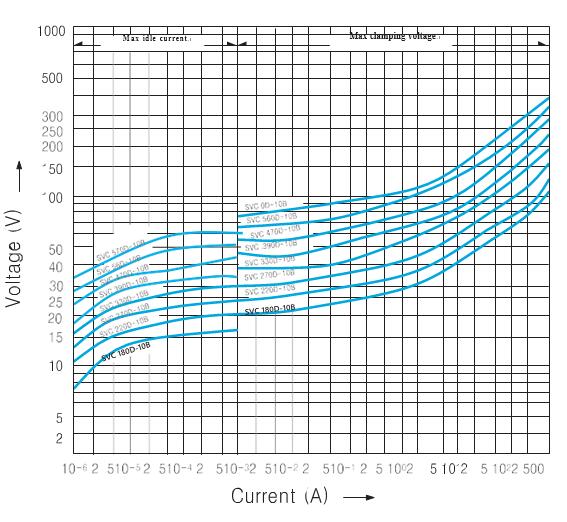
Char, Curves and Lifetime
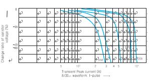
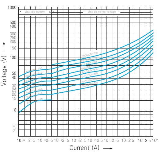
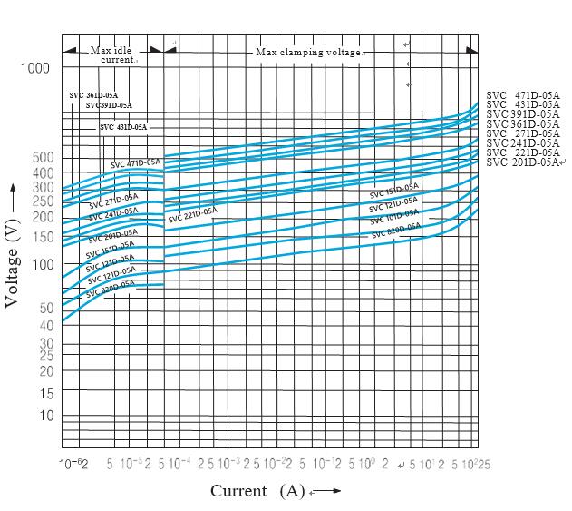
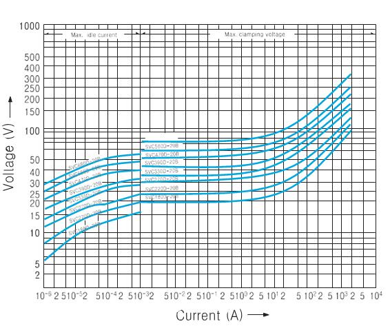
| Transient V-I Charactic Curves Current waveform under 10-2 A : DC over 10-1 A : 8/20㎲ |
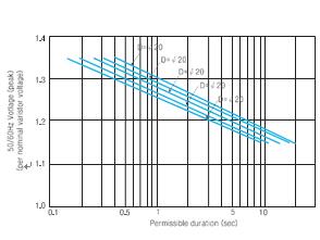
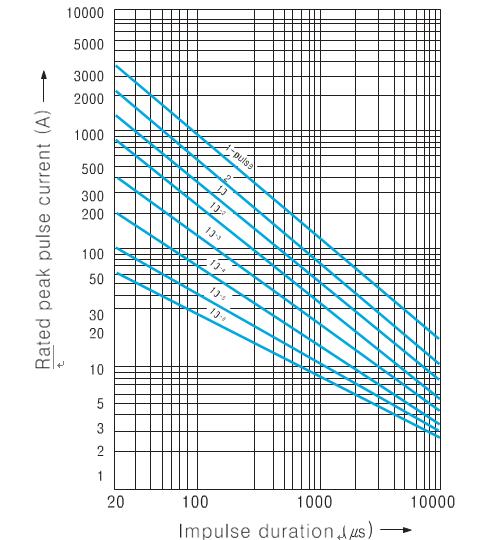
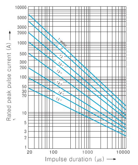
Pulse Lifetime Ratings Notes : 2-pulse : 5-minute interval 3 to 10-pulse : 2-minute interval Up to 106 - pulse : 10-second interval |
| 05B(SVC 180D-05B to SVC 680D-05B) | 05B(SVC 180D-05B to SVC 680D-05B) |
 |
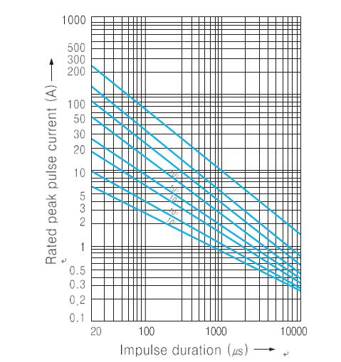 |
| 05A(SVC 820D-05A to SVC 471D-05A) | 05A(SVC 820D-05A to SVC 471D-05A) |
 |
 |
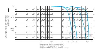
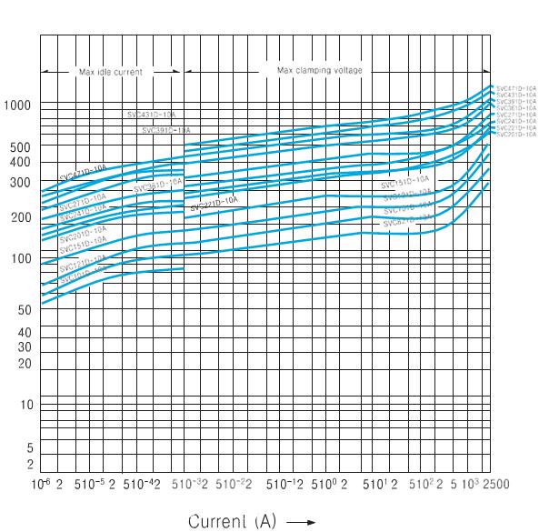
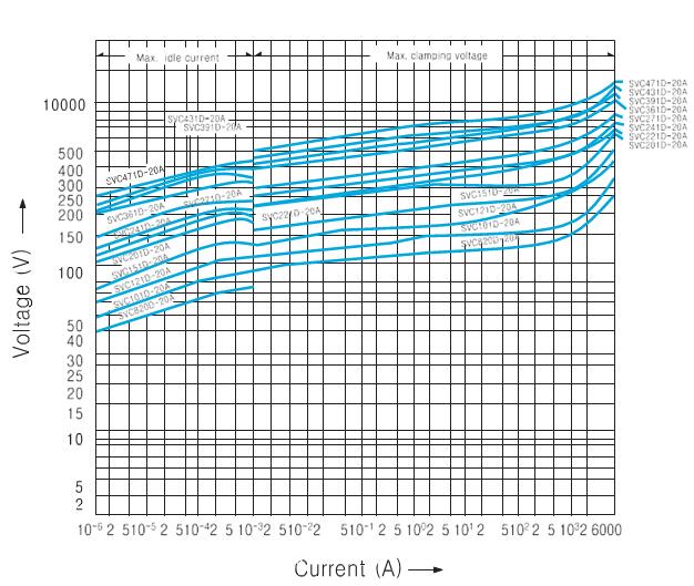
| Transient V-I Characteristic Curves Current waveform under 10-2 A : DC over 10-1 A : 8/20㎲ |
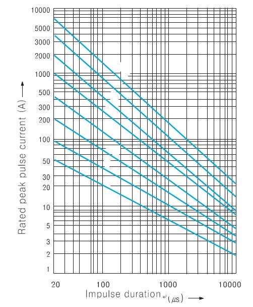
Pulse Lifetime Ratings Notes : 2-pulse : 5-minute interval 3 to 10-pulse : 2-minute interval Up to 106-pulse : 10-second interval |
| 7B(SVC 180D-07B to SVC 680D-07B) | 07B(SVC 180D-07B to SVC 680D-07B) |
 |
 |
| 07A(SVC 820D-07A to SVC 471D-07A) | 07A(SVC 820D-07A to SVC 471D-07A) |
 |
 |
| Transient V-I Characteristic Curves Current waveform under 10-2 A : DC over 10-1 A : 8/20㎲ |
Pulse Lifetime Ratings Notes : 2-pulse : 5-minute interval 3 to 10-pulse : 2-minute interval Up to 106-pulse : 10-second interval |
| 10B(SVC 180D-10B to SVC 680D-10B) | 10B(SVC 180D-10B to SVC 680D-10B) |
 |
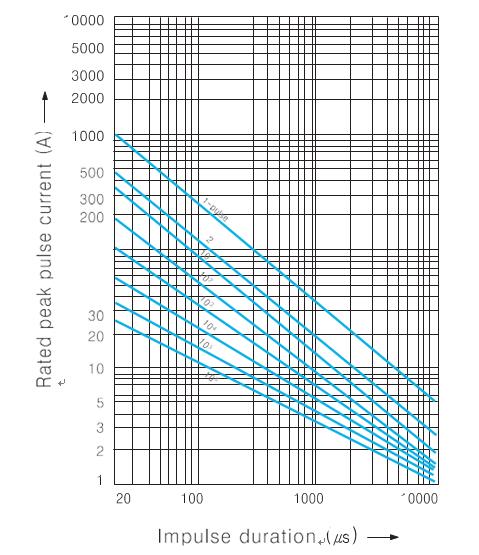 |
| 10A(SVC 820D-10A to SVC 471D-10A) | 10A(SVC 820D-10A to SVC 471D-10A) |
 |
 |
| Transient V-I Characteristic Curves Current waveform under 10-2 A : DC over 10-1 A : 8/20㎲ |
Pulse Lifetime Ratings Notes : 2-pulse : 5-minute interval 3 to 10-pulse : 2-minute interval Up to 106-pulse : 10-second interval |
| 10A(SVC 561D-10A to SVC 112D-10A) | 10A(SVC 561D-10A to SVC 112D-10A) |
 |
 |
| 14B(SVC 180D-14B to ENC 680D-14B) | 14B(SVC 180D-14B to SVC 680D-14B) |
 |
 |
| Transient V-I Characteristic Curves Current waveform under 10-2 A : DC over 10-1 A : 8/20㎲ |
Pulse Lifetime Ratings
Notes : 2-pulse : 5-minute interval 3 to 10-pulse : 2-minute interval Up to 106-pulse : 10-second interval |
| 4A(SVC 820D-14A to SVC 471D-14A) | 14A(SVC 820D-14A to SVC 471D-14A) |
 |
 |
| 14A(SVC 561D-14A to SVC 182D-14A) | 14A(SVC 561D-14A to SVC 182D-14A) |
 |
 |
| Transient V-I Characteristic Curves Current waveform under 10-2 A : DC over 10-1 A : 8/20㎲ |
Pulse Lifetime Ratings Notes : 2-pulse : 5-minute interval 3 to 10-pulse : 2-minute interval Up to 106-pulse : 10-second interval |
| 20B(SVC 180D-20B to SVC 680D-20B) | 20B(SVC 180D-20B to SVC 680D-20B) |
 |
 |
| 20A(SVC 820D-20A to SVC 471D-20A) |
20A(SVC 820D-20A to SVC 471D-20A) |
 |
 |
| Transient V-I Characteristic Curves Current waveform under 10-2 A : DC over 10-1 A : 8/20㎲ |
Pulse Lifetime Ratings Notes : 2-pulse : 5-minute interval 3 to 10-pulse : 2- minute interval Up to 106 -pulse : 10-second interval |
| 0A(SVC 561D-20A to SVC 182D-20A) | 20A(SVC 561D-20A to SVC 182D-20A) |
 |
 |
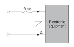
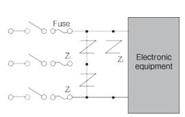
| • The Protection of semiconducting elements such as diodes, thyristors, transistors, IC and relays against transient Voltages. • Similar protection of many types of measuring instruments, control machinery and communication equipment and broadcasting equipment against inductive lightning and switching surges. • Protection of general purpose electrical equipment, domestic mechinery and appliances. TV and radios and similar consumer products against lightning and switching surges. |
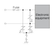
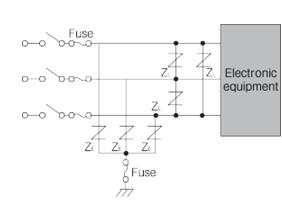
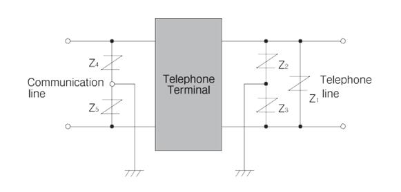
Line and groud circuit Varistor voltage selection table(ZE)
① When subjected to megger testing(500V DC), the insulation resistance value can decrease due to the leakage current of the SVC, To avoid this remove the varistor or use* marked SVC. ② When subjected to dielectric strength test(1000V AC). remove the SVC or use** marked SVC. Select varistors taking a note of operating conditions peculiar to the equipment.
|
| Power Supply Voltage | Type |
| 100VAC | SVC201D -□□A SVC221D -□□A SVC241D -□□A SVC271D -□□A* |
| 200VAC | SVC391D -□□A SVC431D -□□A SVC471D -□□A* |
| 12V DC | SVC220D -□□B |
| 24V DC | SVC390D -□□B |
|
Single-phase circuit |
AC three-phase circuit |
 |
 |
| Power Supply Voltage | Type |
| 12V DC |
SVC180D -□□B SVC220D -□□B SVC820D -□□A |
| 24V AC |
SVC390D -□□B SVC820D -□□A |
| SVC | 05A | 07A | 10A | 14A | 20A |
| 05B | 07B | 10B | 14B | 20B | |
| Applicable fuse rated current(A) | 1 to 2 | 2 to 3 | 3 to 5 | 3 to 10 | 5 to 15 |
|
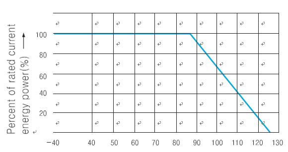
Operating ambient temperature |
-40℃ to +85℃ |
|
Storage temperature |
-40℃ to +125℃ |
|
Voltage temperatur coefficient |
-0.05% ℃ |
|
Insulation resistance(at500V) |
Over 1000MΩ |
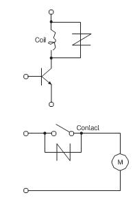
Switching Circuit Protection
| Protection of relay (Contact coil) | Protection of semiconductors |
 |
 |
|
Power Supply Voltage |
Type |
|
12V DC |
SVC220D -□□B |
|
24V DC |
SVC390D -□□B |
|
100V DC |
SVC151D -□□A |
|
100V AC |
SVC201D -□□A |
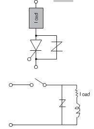
Application Notes
Overcurrent protection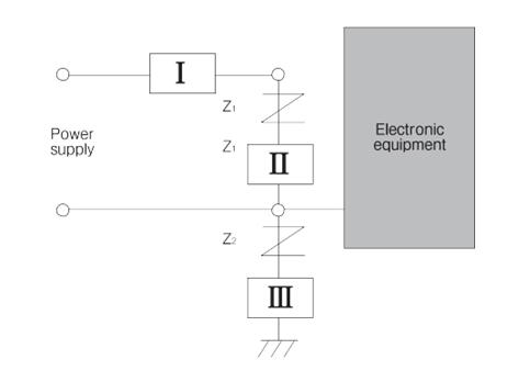
|
Standard |
Content |
Applicable SVC series |
File No. |
||
|
UL |
UL 1449 3rd edition |
Surge-protective Devices - Component |
Other SPD Applications : 05/07/10 Series, 14B/20B Series |
Type 3 SPD Applications : 14A/20A Series |
E332621 |
|
UL 497B |
Component-Isolated Loop Circuit Protectors |
SVC 180D - □~ SVC821D -□ |
E154171 |
||
|
VDE |
IEC61051-1:2007-04 IEC61051-2:1991-01 IEC61051-2-2:1991-01 |
Varistor |
05/07/10/14 Series |
116012 |
|
|
CAS |
CLASS 2221 01 |
AUDIO AND VIDEO EQUIPMENT - Accessories and Parts for Electronic Equipment |
SVC201D - □ ~SVC182D - □ |
1577876 |
|
Fire Alarm System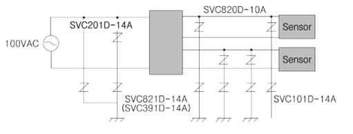 |
Stove, Boiler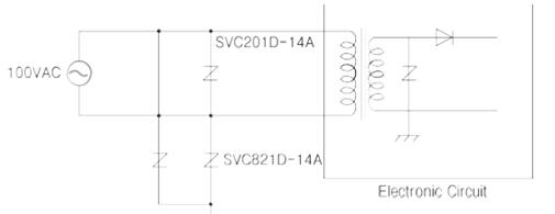 |
Traffic Signal Control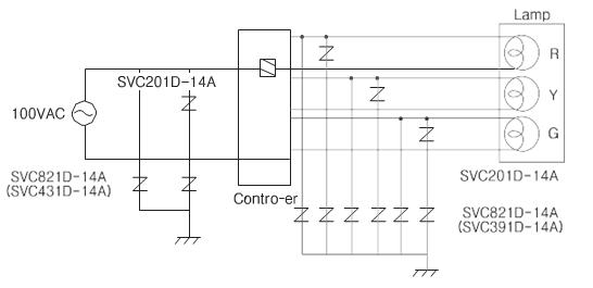 |
Vending Machine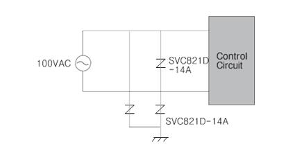 |
Solenoid |
Brake, Clutch |
Contect Protection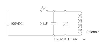 |
Microwave Oven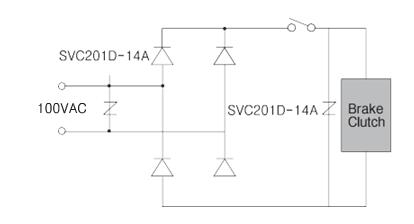 |
Thytister Protection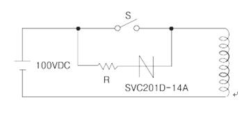 |
Triac Protection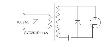 |
TV Booster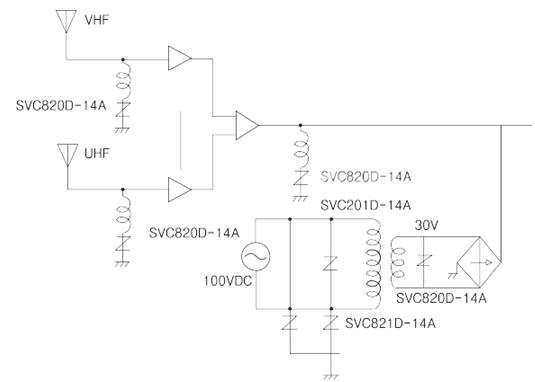 |
Sound Output Circuit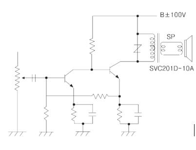 |
Varistor Terminology
| Varistor Voltage : Vnom |
Clamping Voltage : Vc |
| Varistor peak terminal voltage measured with a specified current applied The DC current applied is 1mA normally. Typical values measured at a test frequency of 1kHz 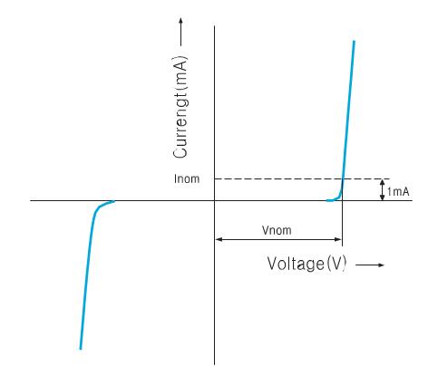 |
Maximum terminal voltage (peak voltage across the varistor) measured with an applied 8/20㎲ impulse of a given peak current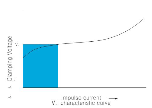 |
|
Rated peak transient current : itm
Maximum peak current through the varistor with line voltage applied.The maximum peak current with in the varistor voltage change ratio of ±10% with the standard 8/20㎲ impulse current applied two times at 5 minute interval |
Test current waveform
Characteristics tests for Varistors are carried out by using 8/20㎲ test impulses Data such as the maximum clamping voltage(Vc)and the transient peak current(Itm) are obtained by using this impulse currentHowever, for the Vc characteristics of the Axial Package type a 10mA DC squarewave current is used to cary out the test. |
|
Rated transient energy : Wtm
Maximum allowable energy for a single impulse of 2ms square-wave current waveform with rated continuous voltage applied. Maximum energy rating base on a shift of Vnom of less than ±10% of initial value.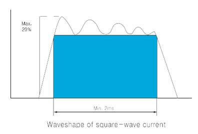 |
 |
|
Pulse lifetime rating
This is expressed as the maximum allowable number of impulse currents applied.8/20㎲ impulse current(or 2ms square wave) is applied at prescribed interval. This curve also provides for derating current as required with repetitive pulsing. 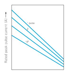 |
Rated RMS Voltage : Vacm Maximum continuous sinusoidal RMS voltage at 50/60Hz which may be applied. Rated DC Voltage : Vdcm Maximum continuous DC voltage which may be applied. Rated average power dissipation : Ptam Maximum average power that can be applied within the specified ambient temperature. |