| Part No | Figure / Lead Option |
lhold (A) | Itrip (A) |
Vmax (V) |
Imax (A) |
Pd typ (W) |
Max. (A) |
Time-to-trip (s) |
R min (Ω) |
R1 Max (Ω) |
|
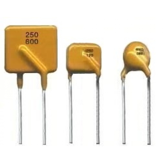
| UBF | RH250080 | Fig. 1, Ø0.51, Sn/CuFe | 0.08 | 0.16 | 100 | 3.0 | 1.0 | 0.35 | 4.0 | 14.5 | 33.0 |
| UBF | RH250110 | Fig. 1, Ø0.51, Sn/CuFe | 0.11 | 0.22 | 100 | 3.0 | 1.0 | 1.00 | 2.0 | 5.0 | 16.0 |
| UBF | RH250120 | Fig. 1, Ø0.51, Sn/CuFe | 0.12 | 0.24 | 100 | 3.0 | 1.0 | 1.00 | 2.0 | 4.0 | 16.0 |
| UBF | RH250145 | Fig. 1, Ø0.51, Sn/CuFe | 0.15 | 0.29 | 100 | 3.0 | 1.0 | 1.00 | 2.5 | 3.0 | 12.0 |
| UBF | RH250180 | Fig. 1, Ø0.51, Sn/CuFe | 0.18 | 0.65 | 100 | 10.0 | 1.5 | 3.00 | 2.0 | 0.8 | 4.0 |
| UBF | RH250150 | Fig. 1, Ø0.51, Sn/CuFe | 0.15 | 0.30 | 250 | 3.0 | 1.0 | 1.00 | 3.0 | 0.6 | 17.0 |
| UBF | RH250160 | Fig. 2, Ø0.81, Sn/CuFe | 0.16 | 0.32 | 250 | 3.0 | 1.0 | 1.00 | 7.0 | 0.4 | 18.0 |
| Ihold | Hold current is the maximum current that UB Fuse can pass through without interruption at 20°C unless otherwise specified. |
| Itrip | Trip current is the minimum current that will switch the device from low resistance state to high resistance state at 20°C unless specified. |
| Vmax | The maximum voltage device can withstand without damage at rated current. |
| Imax | The maximum current device can withstand without damage at rated voltage. |
| Pd | The power dissipated from device when in the tripped state at 20°C unless otherwise specified. |
| R min | The minimum resistance of device as received from the factory at 20°C unless otherwise specified. |
| R max | The maximum resistance of device as received from the factory at 20°C unless otherwise specified. |
| R1max | The maximum resistance of device when measured one hour post trip at 20°C unless otherwise specified. |
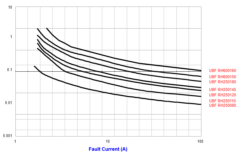
| Max. Time-to-trip |
The maximum time for device to trip at specified current ratings at 20°C unless otherwise specified. |
| Test | Test Conditions | Resistance Change |
| Passive Aging | +85°C, 1000 hours | ±5% typical resistance change |
| Humidity Aging | +85°C, 85% R.H., 7 days | ±5% typical resistance change |
| Thermal Shock | +85°C to -40°C, 10 times MIL-STD-202, Method 107G |
±5% typical resistance change |
| Vibration | MIL-STD-883C, Condition A | No change |
| Solvent resistance | MIL-STD-202, Method 215 | No change |
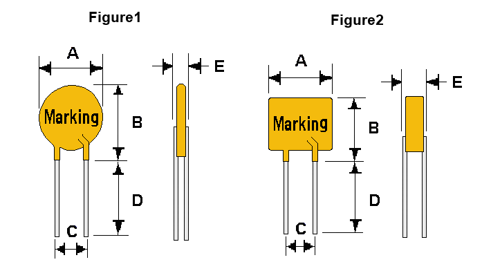
| A | B | C | D | E | F | |
| Part No | Figure | Max. | Max. | Typical | Min. | Max. |
| UBF RH250080 | 1 | 5.8 | 9.6 | 5.0 | 4.7 | 4.6 |
| UBF RH250110 | 1 | 6.8 | 9.9 | 5.0 | 4.7 | 4.6 |
| UBF RH250120 | 2 | 6.5 | 11.0 | 5.0 | 4.7 | 4.6 |
| UBF RH250145 | 2 | 6.5 | 11.0 | 5.0 | 4.7 | 4.6 |
| UBF RH250180 | 1 | 9.0 | 12.0 | 5.0 | 4.7 | 3.8 |
| UBF RH250150 | 2 | 9.0 | 12.5 | 5.0 | 4.7 | 4.6 |
| UBF RH250160 | 2 | 16.0 | 12.6 | 5.0 | 4.7 | 6.0 |
| UL File Number | E 119550 |
| c-UL File Number | E 119550 |
| TUV File Number | Pending |
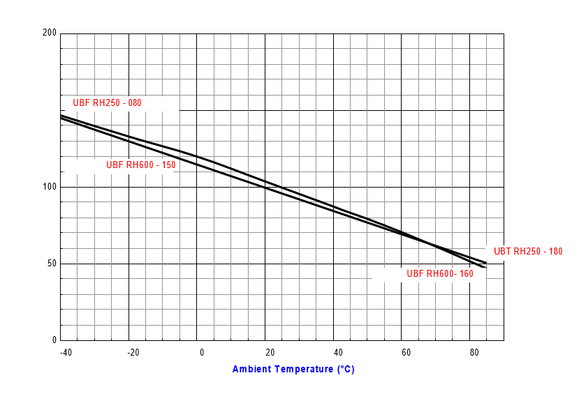
| Part No | -40 | -20 | 0 | 20 | 40 | 60 | 85 |
| UBF RH250080 | 0.13 | 0.11 | 0.10 | 0.10 | 0.07 | 0.05 | 0.03 |
| UBF RH250110 | 0.17 | 0.15 | 0.13 | 0.13 | 0.09 | 0.07 | 0.03 |
| UBF RH250120 | 0.19 | 0.17 | 0.14 | 0.14 | 0.10 | 0.08 | 0.05 |
| UBF RH250145 | 0.24 | 0.21 | 0.18 | 0.18 | 0.12 | 0.10 | 0.06 |
| UBF RH250180 | 0.28 | 0.25 | 0.21 | 0.21 | 0.15 | 0.12 | 0.08 |
| UBF RH250150 | 0.24 | 0.21 | 0.18 | 0.18 | 0.12 | 0.10 | 0.06 |
| UBF RH250160 | 0.25 | 0.22 | 0.19 | 0.19 | 0.13 | 0.10 | 0.07 |
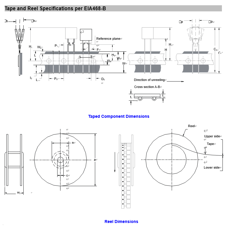
| Part No | -1 Loose Pack Quantity | -2 Tape & Reel Quantity | -3 Ammo Pack Quantity |
| UBF RH250080 | 500 | 3000 | 2000 |
| UBF RH250110 | 500 | 3000 | 2000 |
| UBF RH250120 | 500 | 3000 | 2000 |
| UBF RH250145 | 500 | 3000 | 2000 |
| UBF RH250180 | 500 | 2500 | 2000 |
| UBF RH250150 | 500 | 2500 | 2000 |
| UBF RH250160 | 500 | 2000 | 2000 |