| Part No | lhold (A) | Itrip (A) |
Vmax (V) |
Imax (A) |
Pd typ (W) |
Max. (A) |
Time-to-trip (s) |
R min (Ω) |
R1 Max (Ω) |
|
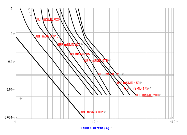
| UBF | mSMD005 | 0.35 | 0.15 | 60 | 10 | 0.6 | 0.25 | 3.00 | 3.600 | 50.00 |
| UBF | mSMD010 | 0.10 | 0.25 | 30 | 10 | 0.6 | 0.50 | 1.50 | 1.600 | 15.00 |
| UBF | mSMD020 | 0.20 | 0.40 | 30 | 10 | 0.6 | 8.00 | 0.02 | 0.800 | 5.000 |
| UBF | mSMD035 | 0.35 | 0.75 | 16 | 40 | 0.6 | 8.00 | 0.20 | 0.320 | 1.300 |
| UBF | mSMD050 | 0.50 | 1.00 | 16 | 40 | 0.6 | 8.00 | 0.10 | 0.250 | 0.900 |
| UBF | mSMD075 | 0.75 | 1.50 | 8 | 40 | 0.6 | 8.00 | 0.10 | 0.130 | 0.400 |
| UBF | mSMD110 | 1.10 | 2.20 | 6 | 100 | 0.8 | 8.00 | 0.30 | 0.060 | 0.210 |
| UBF | mSMD150 | 1.50 | 3.00 | 6 | 100 | 0.8 | 8.00 | 0.50 | 0.040 | 0.110 |
| UBF | mSMD175 | 1.75 | 3.50 | 6 | 100 | 0.8 | 8.00 | 0.60 | 0.020 | 0.080 |
| UBF | mSMD200 | 2.00 | 4.00 | 6 | 100 | 0.8 | 8.00 | 1.00 | 0.015 | 0.070 |
| Ihold | Hold current is the maximum current that UB Fuse can pass through without interruption at 20°C unless otherwise specified. |
| Itrip | Trip current is the minimum current that will switch the device from low resistance state to high resistance state at 20°C unless specified. |
| Vmax | The maximum voltage device can withstand without damage at rated current. |
| Imax | The maximum current device can withstand without damage at rated voltage. |
| Pd | The power dissipated from device when in the tripped state at 20°C unless otherwise specified. |
| R min | The minimum resistance of device as received from the factory at 20°C unless otherwise specified. |
| R max | The maximum resistance of device as received from the factory at 20°C unless otherwise specified. |
| R1max | The maximum resistance of device when measured one hour post trip at 20°C unless otherwise specified. |
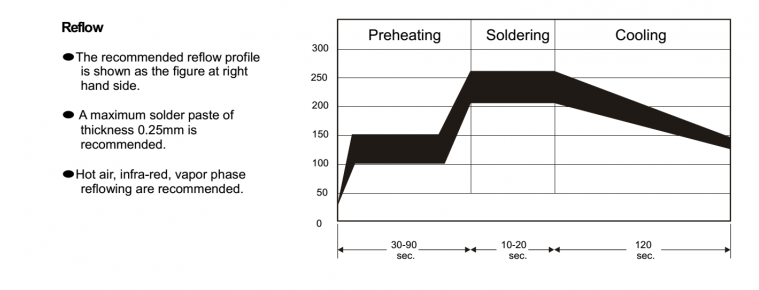
| Max. Time-to-trip |
The maximum time for device to trip at specified current ratings at 20°C unless otherwise specified. |
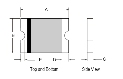
| A | B | C | D | E | ||||||
| Part No UBF mSMD |
Min. | Max. | Min. | Max. | Min. | Max. | Min. | Max. | Min. | Max. |
| 3.00 | 3.43 | 2.35 | 2.80 | 0.60 | 1.15 | 0.25 | 0.75 | 0.10 | 0.45 | |
| UL File Number | E 119550 |
| c-UL File Number | E 119550 |
| TUV File Number | Pending |
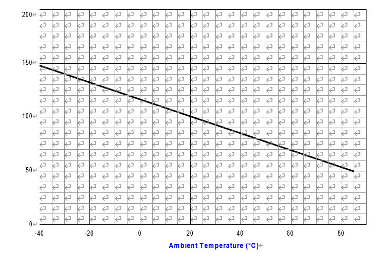
| Part No | -40 | -20 | 0 | 20 | 40 | 60 | 85 |
| UBF mSMD005 | 0.07 | 0.06 | 0.06 | 0.05 | 0.04 | 0.03 | 0.02 |
| UBF mSMD010 | 0.15 | 0.12 | 0.12 | 0.10 | 0.08 | 0.06 | 0.05 |
| UBF mSMD020 | 0.29 | 0.23 | 0.23 | 0.20 | 0.17 | 0.13 | 0.09 |
| UBF mSMD035 | 0.51 | 0.40 | 0.40 | 0.35 | 0.29 | 0.22 | 0.16 |
| UBF mSMD050 | 0.73 | 0.58 | 0.58 | 0.50 | 0.42 | 0.32 | 0.23 |
| UBF mSMD075 | 1.10 | 0.86 | 0.86 | 0.75 | 0.62 | 0.48 | 0.35 |
| UBF mSMD110 | 1.60 | 1.27 | 1.27 | 1.10 | 0.91 | 0.70 | 0.51 |
| UBF mSMD150 | 2.18 | 1.73 | 1.73 | 1.50 | 1.25 | 0.96 | 0.69 |
| UBF mSMD175 | 2.54 | 2.31 | 2.01 | 1.75 | 1.45 | 1.12 | 0.81 |
| UBF mSMD200 | 2.90 | 2.64 | 2.30 | 2.00 | 1.66 | 1.28 | 0.92 |
| Test | Test Conditions | Resistance Change |
| Passive Aging | +85°C, 1000 hours | ±10% typical resistance change |
| Humidity Aging | +85°C, 85% R.H., 7 days | ±10% typical resistance change |
| Thermal Shock | +85°C to -40°C, 10 times MIL-STD-202, Method 107G |
±10% typical resistance change |
| Vibration | MIL-STD-883C, Condition A | No change |
| Solvent resistance | MIL-STD-202, Method 215 | No change |
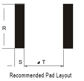
| Part No | R | S | T |
| UBF mSMD050 | 2.50 | 1.00 | 2.00 |
| UBF mSMD075 | 2.50 | 1.00 | 2.00 |
| UBF mSMD110 | 2.50 | 1.00 | 2.00 |
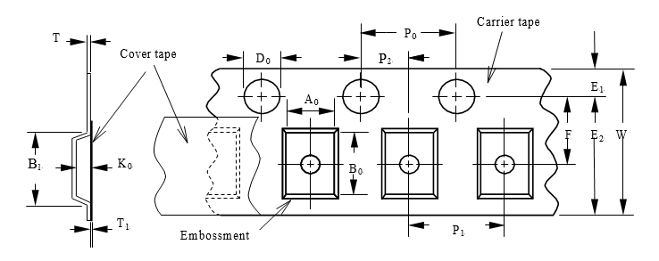
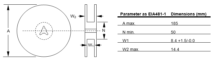
| Parameter as EIA481-1 | Dimensions (mm) |
| W | 8.00 ± 0.30 |
| P0 | 4.00 ± 0.10 |
| P1 | 4.00 ± 0.10 |
| P3 | 2.00 ± 0.05 |
| A0 | 2.95 ± 0.10 |
| B0 | 3.58 ± 0.10 |
| B1max | 4.35 |
| D0 | 1.50 +0.10/-0.00 |
| F | 3.50 ± 0.05 |
| E1 | 1.75 ± 0.10 |
| E2min | 6.25 |
| T max | 0.6 |
| T1max | 0.1 |
| K0 | 0.80 ± 0.10 |