◆FEATURES
●NTC SURGE PROTECTORS of ceramic material are made from specially formulated metal oxides.
The application of NTC SURGE PROTECTORS limits the current to a low value at from on for protection against extremely high peak inrush current in AC/DC power
supplies etc.
● Advanced packaging technology, packaging materials meet UL94-V0.
● Compact structure, small size, space saving.
● Superior high temperature and high humidity performance.
● Strong inhibition of surge.
● SMD tray packaging, suitable for lead-free reflow soldering wave soldering automatic placement.
◆APPLICATIONS
● LED circuit protection LED.
● Industrial Equipment.
● Communication Equipment.
● Consumer Electronics.
● Automotive Electronics.
◆ELECTRICAL (Maximum Ratings)
●Lower Category Temperature : - 40 ℃
●Upper Category Temperature : + 200 ℃
◆STORAGE CONDITIONS
●Storage Temperature : -40℃~ +125℃.
●Relative Humidity : 30~75% RH.
●Thermistor must be kept away from sunshine and stored in a non-corrosive atmosphere.
● Period of storage 1 year.
◆ORDER INFORMATION
| Series Code |
Res. value |
Res. Tolerance |
Max. steady state current |
| USMD |
10 |
M |
□ □ A |
| |
Zero Power Resistance |
|
|
| |
at 25℃ 10Ω |
|
|
◆CHARACTERISTICS
| Part No. |
Zero
Power Resistance |
Max. steady
State Current |
Resistance
At Max. Current |
Thermal
Dissipation
Constant |
Thermal
Time Constant |
“B” Value |
Operating
Temperature Range |
@25℃
( Ω ) |
@25℃
( A ) |
@25℃
( Ω ) |
(mW/℃) |
(Sec.) |
°K |
(℃) |
| USMD-1R5M-1.8A |
1.5 |
1.8 |
0.13 |
>6 |
<20 |
2500 |
-40一+175 |
| USMD-1R5M-2.2A |
1.5 |
2.2 |
0.16 |
>10 |
<30 |
2600 |
-40一+175 |
| USMD-1R5M-4.5A |
1.5 |
4.5 |
0.082 |
>11 |
<35 |
2600 |
-40一+175 |
| USMD-1R5M-5A |
1.5 |
5 |
0.065 |
>13 |
<43 |
2600 |
-40一+175 |
| USMD-1R5M-7A |
1.5 |
7 |
0.073 |
>13 |
<60 |
2600 |
-40一+200 |
| USMD-1R5M-8A |
1.5 |
8 |
0.052 |
>18 |
<69 |
2600 |
-40一+200 |
| USMD-2R5M-1.5A |
2.5 |
1.5 |
0.17 |
>6 |
<20 |
2500 |
-40一+175 |
| USMD-2R5M-2A |
2.5 |
2 |
0.19 |
>10 |
<30 |
2600 |
-40一+175 |
| USMD-2R5M-4A |
2.5 |
4 |
0.113 |
>11 |
<35 |
2600 |
-40一+175 |
| USMD-2R5M-5A |
2.5 |
5 |
0.095 |
>13 |
<43 |
2600 |
-40一+175 |
| USMD-2R5M-6A |
2.5 |
6 |
0.088 |
>13 |
<60 |
2600 |
-40一+200 |
| USMD-2R5M7A |
2.5 |
7 |
0.065 |
>18 |
<76 |
2800 |
-40一+200 |
| USMD-03M-1A |
3 |
1 |
0.19 |
>6 |
<20 |
2500 |
-40一+175 |
| USMD-03M-2A |
3 |
2 |
0.218 |
>10 |
<30 |
2600 |
-40一+175 |
| USMD-03M-3A |
3 |
3 |
0.12 |
>11 |
<35 |
2600 |
-40一+175 |
| USMD-03M-4A |
3 |
4 |
0.1 |
>13 |
<43 |
2600 |
-40一+175 |
| USMD-03M-5A |
3 |
5 |
0.092 |
>15 |
<60 |
2600 |
-40一+200 |
| USMD-03M-6A |
3 |
6 |
0.075 |
>18 |
<76 |
2800 |
-40一+200 |
| USMD-04M-1A |
4 |
1 |
0.308 |
>6 |
<20 |
2500 |
-40一+175 |
| USMD-04M-2A |
4 |
2 |
0.441 |
>10 |
<30 |
2600 |
-40一+175 |
| USMD-04M-3A |
4 |
3 |
0.19 |
>11 |
<35 |
2600 |
-40一+175 |
| USMD-04M-4A |
4 |
4 |
0.15 |
>13 |
<44 |
2600 |
-40一+175 |
| USMD-04M-5A |
4 |
5 |
0.12 |
>15 |
<67 |
2800 |
-40一+200 |
| USMD-04M-6A |
4 |
6 |
0.1985 |
>18 |
<76 |
2800 |
-40一+200 |
| USMD-05M-1A |
5 |
1 |
0.353 |
>6 |
<20 |
2500 |
-40一+175 |
| USMD-05M-2A |
5 |
2 |
0.283 |
>10 |
<30 |
2600 |
-40一+175 |
| USMD-05M-3A |
5 |
3 |
0.21 |
>11 |
<34 |
2600 |
-40一+175 |
| USMD-05M-4A |
5 |
4 |
0.156 |
>13 |
<45 |
2800 |
-40一+175 |
| USMD-05M-5A |
5 |
5 |
0.125 |
>15 |
<68 |
2800 |
-40一+200 |
| USMD-05M-6A |
5 |
6 |
0.112 |
>20 |
<76 |
2800 |
-40一+200 |
| USMD-06M-0.8A |
6 |
0.8 |
0.451 |
>6 |
<20 |
2600 |
-40一+175 |
| USMD-06M-1A |
6 |
1 |
0.386 |
>9 |
<28 |
2600 |
-40一+175 |
| USMD-06M-2A |
6 |
2 |
0.315 |
>11 |
<32 |
2800 |
-40一+175 |
| USMD-06M-3A |
6 |
3 |
0.24 |
>14 |
<47 |
2800 |
-40一+175 |
| USMD-06M-4A |
6 |
4 |
0.17 |
>15 |
<60 |
3000 |
-40一+200 |
| USMD-06M-5A |
6 |
5 |
0.155 |
>20 |
<80 |
3000 |
-40一+200 |
| USMD-08M-0.8A |
8 |
0.8 |
0.675 |
>6 |
<20 |
2600 |
-40一+175 |
| USMD-08M-1A |
8 |
1 |
0.539 |
>9 |
<28 |
2600 |
-40一+175 |
| USMD-08M-2A |
8 |
2 |
0.4 |
>11 |
<32 |
2800 |
-40一+175 |
| USMD-08M-3A |
8 |
3 |
0.255 |
>14 |
<47 |
2800 |
-40一+175 |
| USMD-08M-4A |
8 |
4 |
0.194 |
>15 |
<60 |
3000 |
-40一+200 |
| USMD-08M-5A |
8 |
5 |
0.178 |
>20 |
<80 |
3000 |
-40一+200 |
| USMD-10M-0.7A |
10 |
0.7 |
1.039 |
>6 |
<20 |
2600 |
-40一+175 |
| USMD-10M-1A |
10 |
1 |
0.616 |
>9 |
<27 |
2600 |
-40一+175 |
| USMD-10M-2A |
10 |
2 |
0.458 |
>11 |
<32 |
2800 |
-40一+175 |
| USMD-10M-3A |
10 |
3 |
0.275 |
>14 |
<47 |
2800 |
-40一+175 |
| USMD-10M-4A |
10 |
4 |
0.206 |
>15 |
<65 |
3000 |
-40一+200 |
| USMD-10M-5A |
10 |
5 |
0.18 |
>20 |
<75 |
3200 |
-40一+200 |
| USMD-20M-0.5A |
20 |
0.5 |
1.253 |
>6 |
<20 |
2600 |
-40一+175 |
| USMD-20M-0.6A |
20 |
0.6 |
1.102 |
>9 |
<27 |
2800 |
-40一+175 |
| USMD-20M-1A |
20 |
1 |
0.864 |
>11 |
<30 |
3000 |
-40一+175 |
| USMD-20M-2A |
20 |
2 |
0.512 |
>15 |
<52 |
3000 |
-40一+175 |
| USMD-20M-3A |
20 |
3 |
0.372 |
>16 |
<65 |
3200 |
-40一+200 |
| USMD-20M-4A |
20 |
4 |
0.288 |
>21 |
<86 |
3200 |
-40一+200 |
◆DIMENSIONS
(Unit : ㎜)
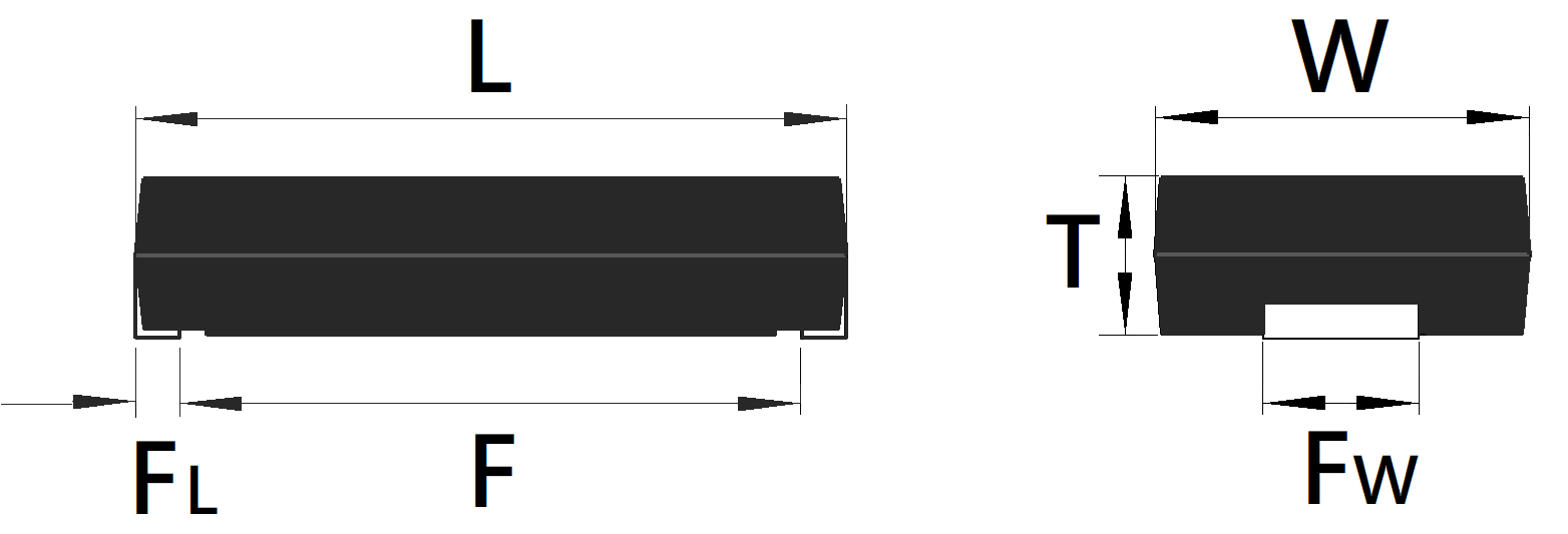
| |
L |
W |
T |
F |
FL |
FW |
| Size(mm) |
11.4 |
6.0 |
2.4 |
10 |
0.7 |
2.5 |
| Tol (mm) |
±0.3 |
±0.3 |
±0.1 |
±0.3 |
±0.3 |
±0.3 |
◆STRUCTURE
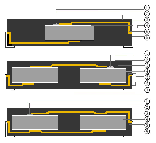
| NO. |
Part name |
Material |
| 1 |
Solder |
Sn-Sb /Sn-Pb-Ag |
| 2 |
Encapsulation Layer |
Epoxy resin (UL94V-0 certified product) |
| 3 |
Electrodes |
Silver/Copper Electrodes |
| 4 |
Insulator Dielectric |
Ceramic Insulator Dielectric |
| 5 |
Internal Pins |
Copper alloy (electronic frame copper) |
| 6 |
SMD Chip Pins |
Tinned Copper |
| 7 |
Intermediate pin in series |
Copper alloy (electronic frame copper) |
◆REFLOW SOLDERING

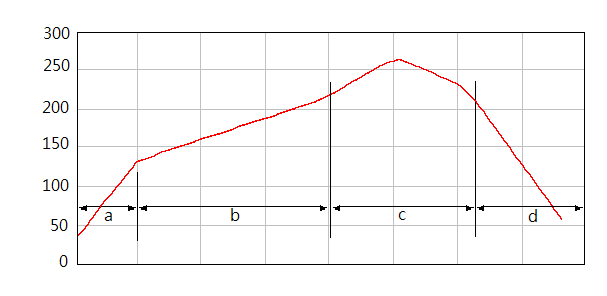
| Zone |
temp. range [deg. C] |
time [sec] |
Remark |
| a |
Curing |
RT ~ 130 |
60
90 ~ 150
90 ~ 150
min 60 |
* Solder : Sn-Ag-Cu
* 260deg. C, over 10sec |
| b |
Preheat |
max 220 |
| c |
Soldering |
220 ~ 260 [max 270] |
| d |
Cooling |
220 ~ RT |
◆TAPING DIMENSIONS
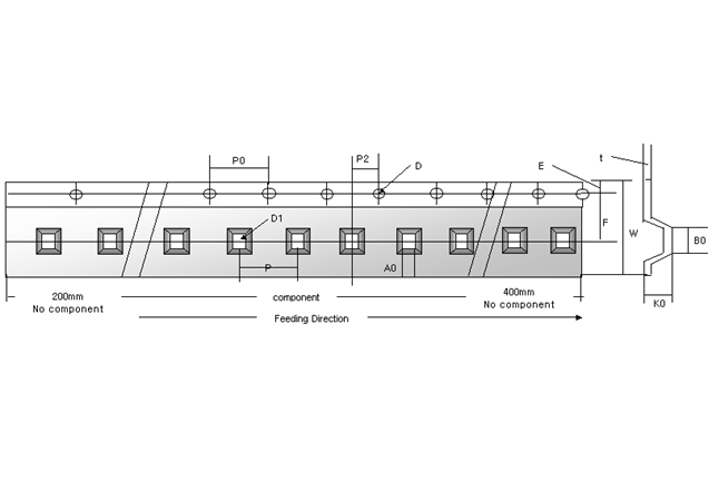 Unit: mm
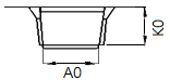
| Reel / Pcs |
A0 |
B0 |
W |
D1 |
E |
F |
P |
P0 |
P2 |
K0 |
| 4000 |
6.5± 0.1 |
12.2±0.1 |
24.0±0.2 |
1.5±0.1 |
1.75±0.1 |
7.5±0.1 |
4.0±0.1 |
8.0±0.1 |
2.0±0.5 |
2.8±0.1 |
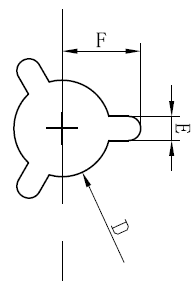
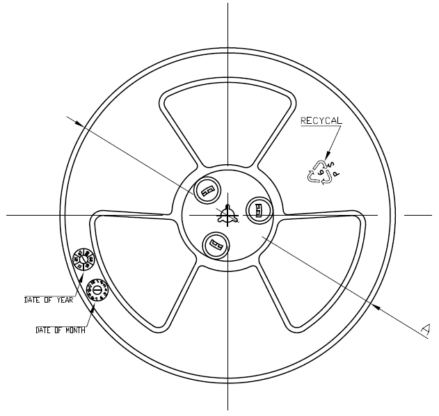
◆REEL DIMENSIONS
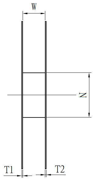
| W |
N |
T1 |
T2 |
A |
D |
E |
F |
| 24.4±0.3 |
Φ100±3.0 |
2.2±0.3 |
2.2±0.3 |
Φ380±3.0 |
13.3±0.3 |
2.3±0.5 |
10.75±0.5 |
◆FAILSAFE
When the NTC is damaged, the failure may cause a short circuit. In order to avoid dangerous
situations such as exit point, smoke, fire, etc. caused by the short circuit, please use the original components such as fuses in the circuit to set the automatic fail-safe function.
If you ignore the above warnings when using this product, it may cause a short circuit in severe cases
and cause smoke or local dispersion.
Warning (Storage and Use Conditions)
The insulating coating of NTC does not have a complete sealing effect; therefore, do not store capacitors
in corrosive gas, especially in the presence of chlorine gas, sulfur gas, acid, alkali, salt, etc.
At the same time should be moisture-proof. Before cleaning, laminating or sealing this product,
please test the performance of the cleaned, laminating or sealing product on the designated equipment
to confirm that the above process will not affect the quality of the product.
This is an MSL3 product. Therefore, to avoid absorbing moisture, moisture-proof packaging is used.
Store the product under the conditions described below and use the product within 6 months of delivery.
Temperature:10to30℃ Humidity:60%max.
Solder capacitors within 168 hours of opening the moisture-proof package. After opening the moisture
-proof package, store the capacitor in the moisture-proof package with desiccant and HIC card, and
keep the above state.
If the storage period of more than 6 months, or the color of the indication of the HIC card included after the package is opened changes, it should be baked before soldering. 60℃*168hr.
When the exposure time of the unpacked product exceeds the exposure life, or other conditions cause the temperature and humidity around the product to exceed the requirements, the reference data for baking after the product humidity before reflow soldering exceeds the requirements (the exposure life after baking starts from zero)
If you ignore the above warnings when using this product, it may cause a short circuit in severe cases and cause smoke or local dispersion.
Warning (Welding, Installation and Use)
●Oscillation and shock
Do not subject the NTC or leads to excessive shock or vibration during use, which will cause fatigue damage to the leads mounted on the circuit board.
The NTC is secured to the circuit board using an adhesive, encapsulant, or other coating. When fixing with designated equipment, please confirm that the fixing measures will not affect the product.
●Welding
When soldering this product to a PCB/PWB, the solder heat resistance specification of NTC must not
be exceeded. Overheating of this product may cause the tin solder to melt at the internal connections, resulting in a sudden temperature change that can crack the ceramic component.
When soldering NTC with a soldering iron, the following conditions should be observed:
Soldering iron tip temperature: up to 400C
Soldering Iron Power: Max 50W
Welding time: up to 3.5 seconds
●Bonding, resin encapsulation and resin coating
Before bonding, sealing, or applying coatings to this product, test the performance of the bonded,
filmed, or coated product on designated equipment to ensure that the above process will not affect
the quality of the NTC.
When the amount and drying/hardening conditions of adhesives and sealing resins containing organic solvents (ethyl acetate, methyl ethyl alcohol, toluene, etc.) are not appropriate, the organic solvents
may damage the outer coating resin of the capacitor, and the worst conditions may cause a short
circuit.
Variations in the thickness of adhesives, sealing resins and organic solvents can also cause cracks
in the resin coating and ceramic components on the capacitor surface during temperature cycling.
●Treatment after bonding, resin encapsulation and resin coating
After soldering, when the outer coating is very hot (over 100C), the outer coating can become very
soft and easy to get drunk.
Here fore, be careful not to apply mechanical shock to the coating.
If you ignore the above warnings when using this product, it may cause a short circuit in severe
cases and cause smoke or local dispersion.
●Precautions (Welding and Installation)
Cleaning (Ultrasonic Cleaning)
When performing ultrasonic cleaning, observe the following conditions:
Sink Capacity: Output 20W or less per liter. Washing time: up to 5 minutes.
Do not oscillate the PCB/PWB directly. Excessive ultrasonic cleaning can lead to lead fatigue damage.